#DIY IS FUN
Hello there fellow Steemians and welcome to my quick tutorial on how to put together a DIY kit I purchased from Banggood that they call a Voice Controlled Melody Light. I enjoy these little DIY kits and have put several together in my time. I find them good soldering practice and I'm relatively new to electronics so I find these kits handy, fun and pleasing.

Step 1: Sort the parts
Every good build begins with organization. I lay out my components so that I can easily grab the part I want as well as confirming I have the correct number of parts.

- 5 LED's
- 1 Microphone
- 1 1μF Electrolytic Capacitor
- 1 22μF Electrolytic Capacitor
- 1 4.7k Resistor
- 1 10k Resistor
- 1 1M Resistor
- 2 9014 Transistors
- 1 2-pin connector
- 1 PCB
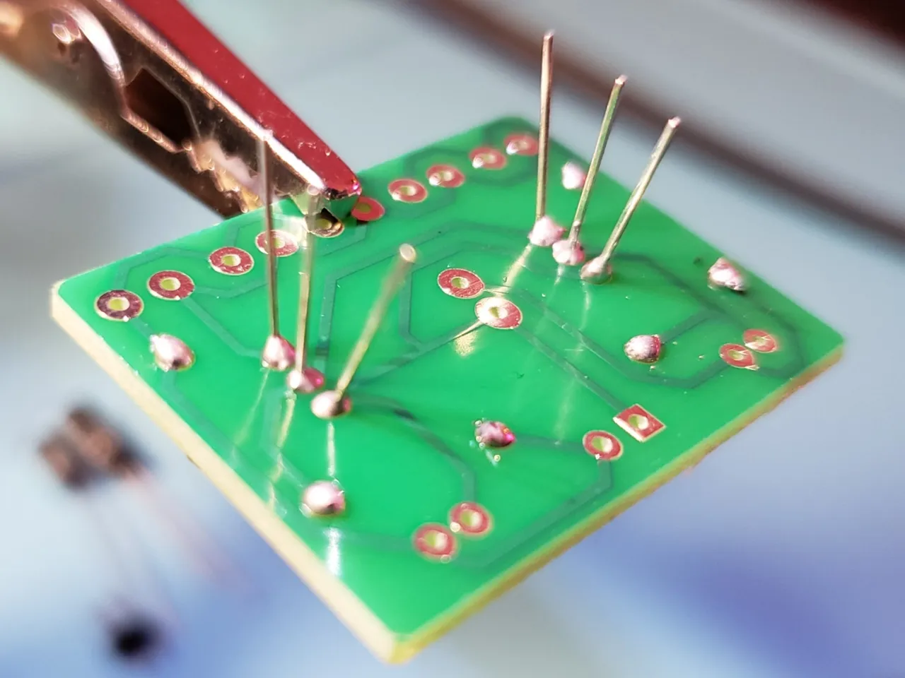
Speaking of the PCB, here's a close up of the top and bottom for you just incase you want to save a few dollars and reverse engineer this!

While I'm not colorblind, I do find reading resistor values to be a royal pain. So I purchased this handy component tester which tells you the value of your resistors as well as many other components. You can also do this with a multimeter. But I find this quick and easy.


Soldering time
Well, since we got those resistors sorted out we might as well start by putting them into the PCB. It's best to tackle the components from smallest to large when the design allows it.
Bend those legs out
Solder them into place
And snip those leads off.
Next up are the two transistors
Be careful soldering these together with the holes being so close together.
Electrolytic capacitors. Mind the polarity. The long lead is positive. The short leg also has a white stripe, which is negative.
Time to slap that microphone in place. By virtue of the design of this PCB and microphone combo, it can only be put into place in the proper direction. If you are reverse engineering this make sure to figure out the polarity of the microphone.
Remember when I said go smallest component to largest? Well, I forgot. And this guy is a bit tricky to hold in place when you're soldering it, but I managed.
Woo, home stretch! Just 5 LED's to go! Remember that LED's have a polarity and the long leg is the anode or positive lead
And finally, apply 5V to the +,- pins


Here is a very short video of the completed module in action. It's quite simple in its design yet rather amusing to mess around with by playing various songs or seeing if the snoring from your pet dog can make it light up.
Thank you for taking the time to read this blog. If you found this trying to find a tutorial on how to put together this Diy Voice Controlled Melody Module, congratulations on completing it.