
This post and video will definitely help you understand What is Line follower Robot , How to make line follower Robot and How does it works. With that, I wanna cover the procedures in making this project , but before I do, I wanna review first what is Robot really means and how important to learn about making robots and programs specially for the future of our technology and society.
Actual video of the final output of the LINE FOLLOWER ROBOT (liitle summary)
Watch the other videos below

Robot refers to any machine or device that carries many complex series of movements, actions and process that programmed automatically by a certain device like Computer
Many of us if was ask what is robot?, actually conclude that it is a machine that was programmed in a human form or humanoid. Or sometimes think that it is a machine that should have faces or arms and perform task like humans can do, but definitely we jsut misunderstood this concept because there are many movies actually shows concept about robots in humanoid form .
Robots are actually any machines that carries a bunch of commands (Programs/Codes) that satisfy our needs, wants or purposes. Robots are not necessarily have eyes like humans or even arms and feet.
In short, Robots can be in different forms as long as it can provide clear response on every command you did on that particular robot or machine.
Robots are very important in our society since it can make our lives more easier and efficient than our normal lives since Robots can follow orders not only for single command but also it can multitask things faster than any regular person.
Learning how to make robots are very important for the innovations of our technology and for the benefits of our society to become more productive and efficient in the future.
⓵ I will also give emphasis about the Parts that this Robot actually made of 👌
⓶ The functions of those every parts 👌
⓷ And ways how to use different software for components simulations and testings 👌
④ What codes are being used in programming for this robot to follow a special task👌
First thing First - What are the materials needed?
♦ Arduino Uno
♦ Breadboard (In making Circuit)
♦ Copper CladBoard (Optional)
♦ Jumper wires
♦ Opto-isolator (Optocoupler sensor)
♦ Resistors (2pcs of 300 ohms and 2 pcs of 10k ohms)
♦ Servo Motor
♦ Battery (4.5v to 5 v)
Software
♦ Fritzing
♦ Livewire
♦ Arduino - Download Here
Short description for the materials
Arduino Uno ⟶ It is a micro-controller board that has inputs and outputs that can be used to store the commands and codes then later will be process by this device.
Breadboard ⟶ It is an electronic tools for experimental purposes where you can make Circuit by experimentally mounting the components, wires and connections temporarily.
Copper CladBoard ⟶ It is a board in different sizes where you can sketch your design circuit connections and etch it for permanent layout and permanent circuit connections.
Jumper Wires ⟶ Wires use for connections to be properly connected and to organize those connections clearly.
Optocoupler sensor ⟶ It is a combination of Photransistor and infrared that uses optical transmission path that when the light of infrared was blocked by a certain object, the optocoupler will give electrical signal to the circuits then it will be activated.
Resistors ⟶ It is an electronic components responsible in controlling the amount of electrical flow in a certain part of Circuit for the desired amount of voltage.
Servo motor ⟶ It is an electronic components that can rotate in degrees and the speed can be adjusted into either slow or fast by some commands through arduino.
Circuit Diagram of a sensor
Open the Livewire Software
Click "Create a Circuit"
Click the gallery or Toolbox in the top menu to view the components and materials that can be use
Then start making your Circuit diagram in live wire.


⒌ Find the components

⒍ This is the final Circuit diagram of the sensors. This procedure was taught to everyone in order to test the circuit for errors. This procedure also very helpful for future project making with regards to Circuitry making.

Circuit Construction of a sensor in BreadBoard
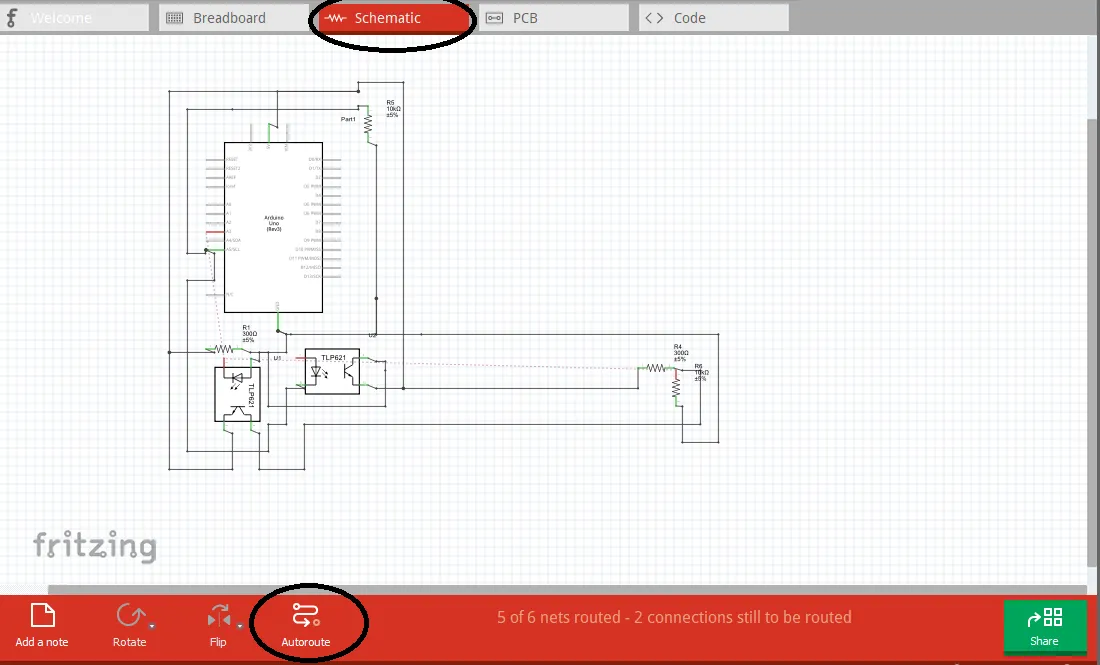
❶ Open the fritzing Software - In this part I'm using other type of electronics software for testing components and circuits for Flexibility purposes 🔥. Also, this procedure is for realistic testing of components connected to arduino.

Beta version can also do the same as the original software
❷ Click on the breadboard

❸ Find and arrange the components
❹ Connect the components as the desired circuit


In real world application :

On this software, you can also check the automatic circuit diagram of the the components you assemble in the breadboard by just clicking the "SCHEMATIC" section and just "AUTO-ROUTE " for the connections.
Here is the Arduino Codes
    #include <Servo.h>
    Servo Left;
    Servo Right;
    const int Lsensor = A3;
    const int Rsensor = A5;
    int Lstate = 0;
    int Rstate = 0;


    void setup()
    {
    pinMode(Lsensor,INPUT);
    pinMode(Rsensor,INPUT);
    Left.attach(5);
   Right.attach(3);
   }
   void loop()
  {
  Lstate = analogRead(Lsensor);
  Rstate = analogRead(Rsensor);
  if ((Lstate>150) && (Rstate>150) )
  {
  Left.attach(5);
  Right.attach(3);
  Left.write(95);
  Right.write(117);

  }
  else if ((Lstate<150) && (Rstate>150) )
  {
  Left.attach(5);
  Left.write(95);
  Right.detach();

 Serial.println();
  }
  else if ((Lstate>150) && (Rstate<150) )
  {
  Right.attach(3);
  Left.detach();
 Right.write(117);
  }
  else if ((Lstate<150) && (Rstate<150) )
  {
  Left.detach();
 Right.detach();
 }

 }
The Line Follower Robot Prototype

The sensors below must be in parallel to each other and must be at least 1 inch in distance. The distance actually depends on the size of the electrical tape being used as the path of the robot.


The Line Follower Robot Actual video
❶. First Testing
As you can see in video, the sensor is in the bottom which is parallel to each other and approximately with a distance of only an inch
❷. Second Testing
If we could refer to humans, sensor serves as the eyes of the robot and the microcontroller Arduino Uno serves as the brain. Once the sensor saw or detected the object (Ground), it will send some information to the brain (Arduino Uno) to execute specific task according to the codes being written in the memory of the Arduino Uno. So, the servo will activated once there is an object detected and stop when there's nothing, a simple logic of high (1) or low (0)
❸. Final Testing
We strongly suggest that the sensor must be parallel correctly with respect to the size of the path (Electrical tape) in order for the sensor to clearly sees the object (ground and tape) below and easily differentiate it whether he (Line follower Robot) can perform logic 1 (HIGH) or low (LOW)
Objective of this project
The main objective of this project is to learn how to logically write codes for the desired task that the robot can perform to follow a certain path. This project is not limited to this application only , thus it depends on your creativity and desires for the innovations of our technology/technologies.
I hope that this will be helpful to everyone specially students and fan of Electronics ❤️

